First things first: What is it good for? Supplying a even flow of DC (direct current) to your electronics project at an expected voltage. ("A clean signal" is the term my favourite electronics repair folks like to throw around.) Granted, this seems pretty obvious on the surface but we tend to take that "even flow" part for granted. Fiddling with electronics -- particularly micro-controllers (MCUs) -- will likely change that.
For relatively simple electronics (e.g. LEDs), it's likely you wouldn't notice that its power supply's voltage level is dropping for a few milliseconds at a time because the human eye can't perceive that. Micro-controllers, in contrast, live microsecond-to-microsecond. A voltage-drop on an input circuit can be interpreted as a sensor being tripped. A voltage drop on the MCU's "Reset" pin will reboot the code uploaded to its memory.
With batteries, these fluctuations generally aren't so much an issue as what happens when the voltage level drops too low. Power supplied by an outlet can be another story but, barring outages, you should only have to worry about this at setup time. (For today's purposes, we're going to rule out any solar-/wind-powered project that doesn't have a rechargeable battery in the mix.)
Let's talk about batteries, though.
Pros:
- Project not tied to an outlet.
- Shouldn't require additional electronics to "clean up" the signal.
- Lithium-Ion and AA, AAA, 9V rechargeable batteries (and a charger) are easy to find & inexpensive relative to the long-term cost of non-rechargeables.
- Calculating current consumption is a good kick in the shins for reading the datasheet.
Cons:
- Require a way to monitor for low battery.
- Project downtime while swapping in freshly-charged batteries.
- Rechargeable AA and AAA cells operate at a different voltage level than alkaline equivalents. (Grrrrr...)
- Not rated for temperatures below the freezing-point.
Personally, I lean on rechargeable NiMH (Nickel Metal Hydride) AA and AAA batteries for everyday electronics anyway, so the up-front cost of the batteries and the charger made sense. One trip to Canadian Tire and done.
AA battery-holders are a common form-factor and come in a variety of capacities: 1, 2, 3, 4, and 6. The holders are dirt-cheap and the ends of the positive and negative leads are generally pre-stripped. Which means that they, in a pinch, can be jammed directly into the positive and negative power-rails of the breadboard. I absolutely do not recommend that -- mainly because you don't have to do it too many times before you mangle the ends. For breadboard prototyping purposes, you (or your favourite electronics repair shop) can solder the raw end of each tip to one end of something called a "male header-pin," and cover the solder-point with shrink-tubing:

Again, this is an option only for the prototyping phase of a project. For a project in active use? Just don't. I stone-cold mean it. That's beyond too dangerous. The "ground" wire coming loose is bad enough; the "positive" wire coming loose means that anything within its range can become its ground wire. That includes you, bee-tee-dubs. And both? [shudder] (The possibility of two loose wires at once is why I like to cut positive leads longer than the negative leads. It's not stupid-proof, mind you, but a little extra insurance doesn't hurt.)
That's where something called a breadboard power adapter comes in. A power adapter is separate from a power supply in that it outputs a DC current but does not generate it. Its header-pins seat into the breadboard at least an order of magnitude more securely the ends of the battery pack's leads. (Sometimes securely enough that seating/unseating the adapter risks bending/breaking header-pins if you're too forceful all at once. This is particularly common with new breadboards.)
In addition to securing the power connection to your breadboard, adapters offer amenities such as:
- Smoothing out ripples in the current. Maybe.
- Providing a "standard" socket (e.g. barrel-jack, USB, JST).
- Providing a specific voltage-level (e.g. 5V, 3.3V).
- (Possibly) including an On/Off switch (something you'll appreciate when the project is in use).
Let's look at a few examples, with their strengths/weaknesses.

This model allows you to power your breadboard via either a 2.1mm barrel-jack or a USB-A male connector. USB generally standardises on 5V. The barrel-jack gives you more flexibility which we'll get to in a bit. Either way, you should figure on your project consuming no more than 500mA of current at any given time.

On the plus side, this style is fairly inexpensive, despite basically being the Cadillac of breadboard power adapters. For mixed-voltage projects, you have the option of powering one side at 5V and the other at 3.3V (a.k.a. 3V3) via jumper-blocks (the yellow rectangles on the left and right).
On the downside, this form-factor is a pig for space. On a full-size breadboard, this will probably be negligible. Half-size breadboards, on the other hand, might require you to break out your Tetris skills. But their biggest drawback, by far, has been their quality. My first batch of five came with one D.O.A. and another bricked the first time I pressed the power-button and heard a fateful "snap" in place of the usual springy "click." (Which is a clue to why I tend to buy them five at a time*.)
And, even with higher-end power-supply, they have a tendency to just wear out over time. In fairness, I use these 24/7 in production, rather than occasional prototyping.
Right. I promised to get back to the barrel-jack power-supply and voltages. As I mentioned, USB pretty much comes with 5V baked in. (Although of course you're going to double-check with your multi-meter, riiiiiiiiiiiight?!?!?!) The barrel-jack is engineered to expect something more than 5V and step it down. Now, if your project is based on 3V3, 5V should probably be okay. But I've had brown-outs with a 5V wall-wart -- a decent-quality one, too. Switching to 9V made that problem go away.
Oh, and before I forget -- make sure your breadboard positive and negative power-rails match the adapter's +/- labels.

This model functions much the same. Fewer bells and whistles mean that it takes up less breadboard space. Same 2.1mm barrel-jack, but the USB connector is a USB-C (a.k.a. "USB micro"). The tiny black slider-switch in the middle toggles between 5V and 3V3 for the entire unit. In other words, both breadboard power-rails operate on the same voltage; you can't cherry-pick like the above model.
To be honest, I have really only used this model for mockups & prototyping, not a Boarduino workhorse. So I can't speak to to the overall quality or longevity of this model. As with its heftier counterpart, make sure that its +/- pins match the red and blue stripes on the power-rails of your breadboard**.
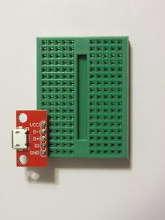
Okay, this is basically a hack. The (Sparkfun) breakout board attached to the mini-breadboard is technically meant to interface with all five potential wires of a USB connection. But that doesn't mean that you can't ignore the middle three pins and use the 5V VCC (positive DC voltage) and GND (negative DC voltage) for your own nefarious (and squee) purposes.
Like all hacks, this is a use-at-your-own-risk kind of deal. Most notably, there is absolutely no reverse-polarity protection. You mix up positive and negative? The "magic smoke" (or worse) is all on you. This will also not doctor the electrical input. Whatever voltage is input will be output. And, probably more important for project stability, there is zero current conditioning -- it will not smooth out drops in voltage or protect you from brown-outs. Now, if you power your project from, say, the USB port on your laptop, this shouldn't be an issue. (Or if it is, you have bigger issues.) Anything else is up to you and your electrical engineering know-how (or lack thereof).
There are other form-factors for these power supplies. Adafruit, for instance, offers one with adjustable output voltage; Sparkfun offers a beefier version of the mini-supply. This is just what I have in my stash at the moment.
Mostly, I've been talking about breadboard adapters in terms of power provided by an outlet via a wall-wart. 2.1mm barrel-jacks tend to be the standard (in North America, anyway). (You might be able to find a wall-wart with a USB-micro connection, but normally you want to save those for your Raspberry Pi) The prevalence -- meaning re-usability -- of the 2.1mm jack, however, is why I would make the rare argument for splurging on higher-end models. The current/voltage that comes from our outlets can be shockingly (pun intended) sloppy. That's why any serious electronics -- including the better wall-warts -- are engineered to clean up the signal.

For battery-powered options, I'd tend to opt for the longevity and and sheer capacity of a Lithium-Ion power stick over NiMH rechargeables. All other things being equal, of course. Your project specs -- milliamp-hours of current, size, temperature, etc. all have to be factored the trade-offs that are engineering.
I'm too lazy to double-check my notes, but I think that the next installment will start to tackle resistors. Until next time, Tchein ton siault d'beluets!
- - - - -
* If that looks like red nail polish on the barrel-jack, you're absolutely correct! This adapter's USB power-supply is the only functioning input. So the red is intended to distinguish this particular unit from others. See what I mean about this style being notoriously flakey right out of the box? :~/
** Yes, breadboard plastic can get that yellow. ABS plastic does that. This workhorse saw some kilometers as the "brains" of a project in continuous service for a couple of years. I've since learned to be more mindful about distributing current-load, trust me.


