Wednesday, March 9, 2022

Widget Wednesday: Breadboard Power Supplies/Adapters

First things first:  What is it good for?  Supplying a even flow of DC (direct current) to your electronics project at an expected voltage.  ("A clean signal" is the term my favourite electronics repair folks like to throw around.)  Granted, this seems pretty obvious on the surface but we tend to take that "even flow" part for granted.  Fiddling with electronics -- particularly micro-controllers (MCUs) -- will likely change that.

For relatively simple electronics (e.g. LEDs), it's likely you wouldn't notice that its power supply's voltage level is dropping for a few milliseconds at a time because the human eye can't perceive that.  Micro-controllers, in contrast, live microsecond-to-microsecond.  A voltage-drop on an input circuit can be interpreted as a sensor being tripped.  A voltage drop on the MCU's "Reset" pin will reboot the code uploaded to its memory.

With batteries, these fluctuations generally aren't so much an issue as what happens when the voltage level drops too low.  Power supplied by an outlet can be another story but, barring outages, you should only have to worry about this at setup time.  (For today's purposes, we're going to rule out any solar-/wind-powered project that doesn't have a rechargeable battery in the mix.)

Let's talk about batteries, though.

Pros:

  • Project not tied to an outlet.
  • Shouldn't require additional electronics to "clean up" the signal.
  • Lithium-Ion and AA, AAA, 9V rechargeable batteries (and a charger) are easy to find & inexpensive relative to the long-term cost of non-rechargeables.
  • Calculating current consumption is a good kick in the shins for reading the datasheet.

Cons: 

  • Require a way to monitor for low battery.
  • Project downtime while swapping in freshly-charged batteries.
  • Rechargeable AA and AAA cells operate at a different voltage level than alkaline equivalents.  (Grrrrr...)
  • Not rated for temperatures below the freezing-point.

Personally, I lean on rechargeable NiMH (Nickel Metal Hydride) AA and AAA batteries for everyday electronics anyway, so the up-front cost of the batteries and the charger made sense.  One trip to Canadian Tire and done.  

AA battery-holders are a common form-factor and come in a variety of capacities:  1, 2, 3, 4, and 6.  The holders are dirt-cheap and the ends of the positive and negative leads are generally pre-stripped.  Which means that they, in a pinch, can be jammed directly into the positive and negative power-rails of the breadboard.  I absolutely do not recommend that -- mainly because you don't have to do it too many times before you mangle the ends.  For breadboard prototyping purposes, you (or your favourite electronics repair shop) can solder the raw end of each tip to one end of something called a "male header-pin," and cover the solder-point with shrink-tubing:


Again, this is an option only for the prototyping phase of a project.  For a project in active use?   Just don't.  I stone-cold mean it.  That's beyond too dangerous.  The "ground" wire coming loose is bad enough; the "positive" wire coming loose means that anything within its range can become its ground wire.  That includes you, bee-tee-dubs.  And both?  [shudder]  (The possibility of two loose wires at once is why I like to cut positive leads longer than the negative leads.  It's not stupid-proof, mind you, but a little extra insurance doesn't hurt.)

That's where something called a breadboard power adapter comes in.  A power adapter is separate from a power supply in that it outputs a DC current but does not generate it.  Its header-pins seat into the breadboard at least an order of magnitude more securely the ends of the battery pack's leads.  (Sometimes securely enough that seating/unseating the adapter risks bending/breaking header-pins if you're too forceful all at once.  This is particularly common with new breadboards.)  

In addition to securing the power connection to your breadboard, adapters offer amenities such as:

  • Smoothing out ripples in the current.  Maybe.
  • Providing a "standard" socket (e.g. barrel-jack, USB, JST).
  • Providing a specific voltage-level (e.g. 5V, 3.3V).
  • (Possibly) including an On/Off switch (something you'll appreciate when the project is in use).

Let's look at a few examples, with their strengths/weaknesses.


This model allows you to power your breadboard via either a 2.1mm barrel-jack or a USB-A male connector.   USB generally standardises on 5V.  The barrel-jack gives you more flexibility which we'll get to in a bit.  Either way, you should figure on your project consuming no more than 500mA of current at any given time.


On the plus side, this style is fairly inexpensive, despite basically being the Cadillac of breadboard power adapters.  For mixed-voltage projects, you have the option of powering one side at 5V and the other at 3.3V (a.k.a. 3V3) via jumper-blocks (the yellow rectangles on the left and right).  

On the downside, this form-factor is a pig for space.  On a full-size breadboard, this will probably be negligible.   Half-size breadboards, on the other hand, might require you to break out your Tetris skills.  But their biggest drawback, by far, has been their quality.  My first batch of five came with one D.O.A. and another bricked the first time I pressed the power-button and heard a fateful "snap" in place of the usual springy "click."  (Which is a clue to why I tend to buy them five at a time*.) 

And, even with higher-end power-supply, they have a tendency to just wear out over time.  In fairness, I use these 24/7 in production, rather than occasional prototyping.  

Right.  I promised to get back to the barrel-jack power-supply and voltages.  As I mentioned, USB pretty much comes with 5V baked in.  (Although of course you're going to double-check with your multi-meter, riiiiiiiiiiiight?!?!?!)  The barrel-jack is engineered to expect something more than 5V and step it down.  Now, if your project is based on 3V3, 5V should probably be okay.  But I've had brown-outs with a 5V wall-wart -- a decent-quality one, too.  Switching to 9V made that problem go away.

Oh, and before I forget -- make sure your breadboard positive and negative power-rails match the adapter's +/- labels.


This model functions much the same.  Fewer bells and whistles mean that it takes up less breadboard space.  Same 2.1mm barrel-jack, but the USB connector is a USB-C (a.k.a. "USB micro").  The tiny black slider-switch in the middle toggles between 5V and 3V3 for the entire unit.  In other words, both breadboard power-rails operate on the same voltage; you can't cherry-pick like the above model.

To be honest, I have really only used this model for mockups & prototyping, not a Boarduino workhorse.  So I can't speak to to the overall quality or longevity of this model.  As with its heftier counterpart, make sure that its +/- pins match the red and blue stripes on the power-rails of your breadboard**.
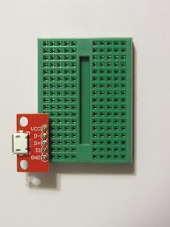


Okay, this is basically a hack.  The (Sparkfun) breakout board attached to the mini-breadboard is technically meant to interface with all five potential wires of a USB connection.  But that doesn't mean that you can't ignore the middle three pins and use the 5V VCC (positive DC voltage) and GND (negative DC voltage) for your own nefarious (and squee) purposes.

Like all hacks, this is a use-at-your-own-risk kind of deal.  Most notably, there is absolutely no reverse-polarity protection.  You mix up positive and negative?  The "magic smoke" (or worse) is all on you.  This will also not doctor the electrical input.  Whatever voltage is input will be output.  And, probably more important for project stability, there is zero current conditioning -- it will not smooth out drops in voltage or protect you from brown-outs.  Now, if you power your project from, say, the USB port on your laptop, this shouldn't be an issue.  (Or if it is, you have bigger issues.)  Anything else is up to you and your electrical engineering know-how (or lack thereof).

There are other form-factors for these power supplies.  Adafruit, for instance, offers one with adjustable output voltage; Sparkfun offers a beefier version of the mini-supply.  This is just what I have in my stash at the moment.

Mostly, I've been talking about breadboard adapters in terms of power provided by an outlet via a wall-wart.  2.1mm barrel-jacks tend to be the standard (in North America, anyway).  (You might be able to find a wall-wart with a USB-micro connection, but normally you want to save those for your Raspberry Pi)  The prevalence -- meaning re-usability -- of the 2.1mm jack, however, is why I would make the rare argument for splurging on higher-end models.  The current/voltage that comes from our outlets can be shockingly (pun intended) sloppy.  That's why any serious electronics -- including the better wall-warts -- are engineered to clean up the signal. 


For battery-powered options, I'd tend to opt for the longevity and and sheer capacity of a Lithium-Ion power stick over NiMH rechargeables.  All other things being equal, of course.  Your project specs -- milliamp-hours of current, size, temperature, etc. all have to be factored the trade-offs that are engineering.

I'm too lazy to double-check my notes, but I think that the next installment will start to tackle resistors.  Until next time, Tchein ton siault d'beluets!

- - - - - 

* If that looks like red nail polish on the barrel-jack, you're absolutely correct!  This adapter's USB power-supply is the only functioning input.  So the red is intended to distinguish this particular unit from others.  See what I mean about this style being notoriously flakey right out of the box? :~/

** Yes, breadboard plastic can get that yellow.  ABS plastic does that.  This workhorse saw some kilometers as the "brains" of a project in continuous service for a couple of years.  I've since learned to be more mindful about distributing current-load, trust me.

Wednesday, March 2, 2022

Widget Wednesday: Wiring

 First things first:  What is it good for?  Actually, two things:

  1. Connecting widgets to the tie-points (i.e. holes, a.k.a. "pins") on a breadboard
  2. Connecting the breadboard tie-points to each other to make complete circuits

 For "Boarduino" purposes, there are two (realistic) options:

  • Flexible jumper-wire
  • Solid-core AWG wire

Let's break down the differences, which are almost-but-not-quite diametrically opposed.

  • Flexible wire is ideal for prototyping.
  • Flexible wire is also fine when you have to connect a breadboard-hostile widget to your project.
  • Solid-core AWG wire is what you use to connect breadboard pins for a project in full-time, real-world use.

In case it isn't obvious right now, you're going to want a mix of both kinds in your kit.

Flexible jumper-wire:  This is made for prototyping and not real-life.  Mostly.  The exception is when the widget doesn't actually plug into the breadboard.  That situation might or might not come with additional issues.  We'll get to those in a bit.

This kind of jumper-wire, under the coloured plastic coating, is actually a bunch of very fine copper wires.  Which is is less likely to break.  But, in my experience, it does like to degrade.  

"War-story":  I was experimenting with something called a Serial-to-Parallel chip to try and control 8-16 LEDs with an Arduino by way of three wires.  Problem was that one of the wires was going wonkier by the minute.  Well, no.  Problem was that I'm a programmer by trade.  So if anything goes wrong, my first instinct is to blame my code.  (Second instinct is to blame file/folder/network permissions, but that doesn't apply here.)

Ultimately, I had the great, good luxury of having an extra breadboard and enough extra widgets to duplicate my setup.  The second version worked flawlessly.  So I methodically replaced each wire in the original breadboarding project and realised that I had a bad one.  The wires weren't even that old, but it's not like they come with an UL rating, either.  So lesson learned.  (End of "war-story.")

Back to those "additional issues."  Off the top of my head, I can think of two widgets that I can only describe as "breadboard-hostile."  One is a common version of the passive infrared (PIR) sensor.  There are two of them below, so that you can see the underside and top-side of the unit.  The top-side (right side) is the lens that acts sort of like an eyeball; the brains -- including the header-pins that connect the sensor to the rest of your project are on the bottom of the board (left side).

The header-pins are the yellow bits near the middle of the pair.  Solid, clearly-labeled header-pins...blocked by two capacitors.  (If you don't know what capacitors are, don't worry; we'll get to that, too.  Just not today.)  

Everyone associated with this board's design is a jerkface.  Not only can you not plug this widget into a breadboard, even a printed circuit-board would have to be designed around this layout-felony.  

It doesn't have to be this way.  The first PIR sensor I ever ordered certainly wasn't this way.  But some slovenly, bean-counting dweeb decided that their rat-race-to-the-bottom retailers could shave $0.00000000000001 off the cost of each unit by massively inconveniencing their customers.  A pox and a plague and a sock-eating dryer upon everyone responsible for this travesty.  (Did I mention that these people are jerkfaces?)

Anyhoo.  Sometimes this sort of stupidity can be turned into a virtue.  But in this case it was only because I had a variety of jumper-wires on-hand.

As some of my Gentle Readers know, my very first real-world Arduino project was designed to teach our omnivorous ElderCat to stay off the counters. 

And, while Mister Kitty is not exactly the sharpest tool in the shed, it only took it three rounds with this thing to convince him that his hoomins were onto him.  (After ten years of yelling and squirt-guns and locking him in the basement after hearing the tell-tale "thump" of his paws hitting the kitchen floor, you're darned tootin' I'm patting myself on the head for that breakthrough.)

The mechanics of this setup are pretty straightforward:

  • Top right is the Arduino-ish Adafruit "Trinket" that is the brains of the outfit.
  • The green board at the bottom-left is a passive infrared (PIR) sensor that detects deviations from the ambient temperature (i.e. a warm, moving body) w/in 3-4 meters
  • The black button is a piezzo buzzer -- a crude audio speaker.

When the PIR sensor detected a warm body in motion w/in the 3-4 meter range, the Trinket fired off a sequence of timed electrical pulses which made the piezzo buzzer play Looney Tunes Tweety-Bird's "I Taught I Taw A Puddy-Tat."  And -- dude! -- it was loud.  Which, of course, was the point.


But at the time, we hoomins weren't certain that it would be that easy to convince Mister Kitty that he was being watched.  Also, it didn't take much for either of us to trigger this thing.  And we probably levitated as much as Mister Kitty.  Clearly, we needed a bit more precision.  So I added something called an ultra-sonic range-finder, which acts somewhat like a bat's echo-location.  

In the Mark II version, the PIR sensor detected a warm body moving somewhere in that 3-4 meter range and only then did the Arduino trigger the range-finder to determine whether there was a solid body within a half meter or so away.  Only when those two conditions were met would the piezo element sing its loony-tune to tattle.  

Muuuuuch less levitation on the part of the hoomins.  And after a month or so, the Mark II followed its predecessor into honourable retirement.


Problem was, the 2nd PIR sensor I bought came with that obnoxious, breadboard-hostile layout.  Which is why, in this case, you see it attached to the rest of the project via an umbilical cord of jumper-wires.  But it turned out to be the proverbial blessing in disguise in that also gave us more flexibility in how we could orient the PIR sensor and the ultrasonic range-finder.  Otherwise, we'd be limited to 90-/180-/270-degree angles.  There might be folks in this world with such geometrically-pure lines of sight on their kitchen counters.  Those people are psychopaths who Doordash all three meals. ;~P

And, as much as an chick raised as an anglophone during the 1970s rolls her eyes at the notion of anything under the sun -- including electronics and language -- being gendered, flexible jumper-wires are labelled with three gender-pairings [thumbs nose].  

  • M/M wires have "male" (i.e. solid wire) headers on both ends.  Because they cover at least 90% of prototyping, you will likely get far, far more mileage out of these than the other two kinds.  Stock up accordingly, 
  • M/F wires are...hermaphroditic.  A solid wire on one end and a matching socket on the other. Again, sometimes you need to connect widgets off-board; these are your play.  Those both came into play with the examples above.  Again, stock up accordingly.
  • F/F have the socket on both ends.  Thus far, I can't recall needing any.  But I can recall being a few $CDN short of the threshold for "free" shipping, and so the small handful I have were basically "free." [shrugs]

Regardless of form-factor, jumper-wires (like the solid-core wires we'll be talking about shortly) come in a rainbow of colours.  In the language of electrical engineering, a few colours matter.  Like far too many other things, which country/region you live in determines the norm.  In this (Canadian) series, we're dealing exclusively with two colours/functions:

  • Red == Positive
  • Black == Ground (functionally equivalent to Negative for our DC purposes)

Norms (and consistency) matter -- particularly when you need someone else's help debugging a layout.  Beyond that, it's up to personal preference.  Shocking precisely no one, I have a couple of those:

  • The "warm" colours (orange, yellow, white) I use for "output."  In practice, that means things like lighting up an LED, buzzing a Piezo element, controlling some sort of motor, what-have-you.
  • The "cool" colours (blue, green, purple) I use for "input."  In practice, that means things like listening for the user to press a button, reading a sensor-value, what-have-you.

Again, that's personal preference.  But it's worked out pretty well so far.  Especially when one of my creations stops working and I haven't looked at it in awhile.  Like every person with a full-time job, debugging my personal projects is done in one-/two-/maybe-three-if-I'm-lucky-hour bursts.  Colour-coding in the here-and-now is a priceless gift from Present Me fiddling on a weekend to Future Me trying to get something up and running before bedtime on a weeknight.  'Nuff said.

Okay, assuming that you're done with prototyping and ready to put your invention into real-world use, AWG-based wiring, by laying flush with the breadboard, is far, far less likely than even a short jumper-wire to be accidentally pulled out where it could become a menace. 

Solid-core American Wire Gauge (AWG) wire:  Again, first things first.  AWG22 wire is your no-brainer breadboarding go-to.  In a pinch, you can probably get away with AWG20 (which, incidentally, is thicker than AWG22, not thinner).  There will be more wear & tear on your breadboard, but if that's all you can find down at the local hardware or auto parts store, it will get you through until you can order 22-gauge. 

Whatever else you do, give the pre-formed wire-kits a big ol' pass. #DoAsISayNotAsIDid  The reason being is that pre-formed wire is colour-coded by length, not function.  We'll deal with why that's a problem in just a bit.

Now.  The thing with AWG wire (of any gauge) right off the roll is that you will need an extra tool -- more likely two tools -- to work with it.  First and foremost is a wire-stripper to separate the insulating plastic from the conductive metal.   Any self-respecting wire-stripper will come with a variety of notches (corresponding to different gauges) plus a wire-cutter built in at the rear of its "jaw."

Because you're already expecting to work in AWG22, my strong recommendation is to permanently mark the 22 "notch."  Grab a tooth-pick and break out (or borrow) a bottle of nail-polish.  Bright red, hot pink, baby-blue, glitter-gold -- whatever will stand out against the dull black or maybe dull silver of the jaws.  Dunk ~1cm-worth of toothpick into the nail-polish and use it as a pen to draw a stripe parallel with the "22" groove on all four sides of the notch.  Then there should never be any ambiguity about which notch you're using to strip the wire.  Because when your wire-stripper includes finer gauges (e.g. AWG24, AWG26, etc.), "ambiguity" can mean that you cut your wire where you meant to strip it.  Ask me how I know.  :~/

When you're cutting wires for breadboarding, you will probably also want basic needle-nose pliers to bend the wire at right angles.  Yes, you might be able to skip the pliers and do this with your fingers.  Assuming that you're, um, blessed with something like the ten scrawny won't-last-a-day-after-The-Apocalypse twigs that my DNA gave me.  And even I prefer the precision of pliers  Pony up a few bucks at Home Hardware and call it a day, already.

Cutting wires for breadboarding has a learning-curve (albeit shallow).  But because I hate waste as much as I love you, I'll try to save everyone a few cm of wasted wire and go over my technique here in a "FWIW" spirit:

  1. With the wire-stripper, strip just under 1cm of coating from the free end of the wire.  My go-to technique is to grab onto the wire where I want to cut the plastic and twist the cutting edge of the notch around the wire core to ensure I cut through all the coating. 
  2. Insert the stripped ~1cm of wire into the "From" breadboard tie-point/pin.
  3. Bend the wire at a 90-degree to lie flush with the breadboard. 
  4. Stretch the wire to the "To" breadboard tie-point.
  5. Bend the wire at a 90-degree angle north of the breadboard -- i.e. the loose end of the wire should point up.
  6. Clip the free end of the wire ~1cm above the surface of the breadboard.
  7. Temporarily remove the "From" end of the wire from the breadboard to make the wire easier to finish off.
  8. Strip the coating off the "To" end of the wire from about half-way into the curve.
  9. Using your needle-nose pliers, bend the newly-stripped wire 180 degrees.
  10. Insert both ends of the wire into the breadboard tie-points.

(Bee-tee-dubs?  The same colour-coding principles as flexible wires apply.)

Once you have cut, stripped, and formed AWG jumper-wire, it tends to be less reusable than the flexible wires used for prototyping.  So until you develop an instinct for breadboard layout, you can save yourself a bunch of scrap by virtually breadboarding your project.  I talked about a couple of options (Tinkercad and Fritzing) toward the end of the "Breadboards" installment.  If you haven't checked them out yet, please do.

Next time, I want to talk about options for powering breadboarded projects.  Until then:  Tchein ton siault d'beluets!

Wednesday, February 16, 2022

Widget Wednesday: Breadboard Basics

As much as I lost my heart to -- and built my first Arduino project on -- Adafruit's Trinket, the game-changer (for me) was stumbling across the chip-on-board form-factor.  That form-factor is not unique to the Arduino universe, where it's sometimes called "Boarduino."  We'll get to that in a later post.  For now, however, I want to focus on the mechanics of the breadboard itself.  Because [extremely schmoozy voice] that's where the magic happens [/extremely schmoozy voice]

First things first:  What is it good for?  "Prototyping" is the obvious answer.  But, chez fivechimera, there's also a long -- and sometimes even honourable -- history of prototypes being "good enough" for literal years of full-time use. Until they're not and the parts go back into their Cabela's tackle-boxes for next time.

This is not a novel concept: "Breadboarding" gets its name from the days of yore -- by which I mean literally a hundred years ago -- when you wired up your project by literally pounding nails into a breadboard (or any wide slab of wood), and winding copper wire around them to create a circuit.  Homebrew ("cat's whisker") radios were a Very Big Deal.  (See also: https://www.mikeselectronicparts.com/wp-content/uploads/building-a-crystal-radio.pdf)  

But, doubtless, one big selling point in those pre-Radio Shack days, was that once that project's usefulness ended, one could always pry loose the widgets, un-string the wire for later use (copper is expensive, y'all!), and pull the nails from the breadboard to restore it to its blank-canvas state.

And so reusability is the main reason I prefer the Boarduino form-factor.  Assuming that you're working w/in certain constraints, reducing project footprint is the second-best reason.  Assuming, of course, that the project can live inside certain limitations:

  1. Current limitations:  Each small hole (a.k.a. "tie point," a.k.a. "pin") on a solderless breadboard should never carry more than 500mA, or 1/2 of an Amp. of current through it.  Theoretically, they can take up to one Amp.  Just don't.  Most especially projects that will be up and running for awhile.  It's not worth the risk.
  2. Voltage limitations:  Stick to 5 volts DC.  Again, you want to stay well within the safety zone.  
  3. Pin spacing:  If the widgets you're planning to plug into your breadboard don't have pins 2.5mm (or 0.1 inch) apart, you're going to need to make other wiring arrangements.  We'll get to those options in a subsequent post.
  4. "Stupid-proofing":  Nothing in a breadboard's construction limits current polarity.  By which I mean, if you mix up positive and ground, the breadboard will not step in to save you.  At best, your project just won't work.  A short can melt the breadboard plastic.  (Ask me how I know.)  You also risk frying any widget connected to the faulty wiring -- up to and including the microcontroller.
  5. Layout limitations:  Do you have enough room on the breadboard for the microcontroller chip (a.k.a. MCU) and all your widgets?  If not, how are you going to work around that when your project is up and running in the real world?

Which brings me to breadboard sizes and their features (or lack thereof).  There might be a few exotic outliers, but here's the range I've stumbled over through the last few years:


I would say that they come in all shapes and sizes, except that the shape is limited to rectangular.

Half-size (top left):  In my experience, this is usually the optimal size for a Boarduino projects. The holes ("pins") come in two flavours.  


  • The two rows that run (horizontally) along the long edges of each side are often referred to as "power rails."  Traditionally, red is connected to the positive end of the power source and runs, uninterrupted from one end to the other.  Ground is wired into blue.  By default, the power rails on each side are independent of each other.
  •  If we consider the power rails to be "rows," then the other flavour of pins can be considered "columns."  These run perpendicular to the rails.  The five pins of each column -- highlighted in neon green -- are connected to each other.  They are not, however, connected to the column on the other side of the trench that runs between them.  

Full size (right):  Similar to the half-size with more "tie points" and often more flexibility.  Depending on the manufacturer, you might need to bridge the two halves of the power-rails.  Or not, depending on your project layout.

Mini (middle left):  In this case, there are no power-rails "rows"; only "columns" of five interconnected pins.  You will have to use one column for a positive rail and one for the negative.  Which brings one big no-no:  Never, EVER wire positive and negative into the same column.  Even for the simplest project.

Micro (bottom left, shown top and bottom):  For grins, I'm throwing this one in.  And, no, I have no idea what's going on with those "Lego-bumps" on the underside except to guess that they allow the breadboard to be glued/screwed into place from the underside of some project???  Again, I have no idea.

Now.  All of the above assumes that you have some basic understanding of how circuits work.  If you're still new to the concepts and/or hesitant to play with live electricity, you can "practice" your wiring skills virtually. 

Most electronics prototyping/visualisation software is geared for PCBs -- printed circuit boards.  That's both an intermediate/advanced move as well as one more or less alien to this feature's "Boarduino" focus.  If you're serious about electronics design, you will need to learn how to "think" in PCB.  For now, don't worry about it.  In practice, that leaves two non-trivial options:

TinkerCad is "free" in the sense that you can give AutoDesk your email address -- be sure to use the "spam" one -- and play around in the "Electronics" section to see what I mean.  

  • Pros:  It's "free" in the sense that you're giving a large company your email address and the user interface is quite intuitive.  Also, it's online, so no PC-vs.-Mac-vs.-Linux issues to worry about
  • Cons:  AutoDesk offers shockingly small range of "widgets" to plug into the breadboard.   

Fritzing is payware.  (Normally, I'm more than happy to trade money-for-value...until that money is processed by [spits] Paypal.)

  • Pros:  A much, much broader variety of widgets.  Some vendors (wisely) contribute to the Fritzing project; others don't.  But you can normally find something "close enough."
  • Cons:  A slightly steeper -- if unsurprising -- learning-curve because there are more features.  (Pro tip:  Save yourself a bunch of grief and learn how to "lock" main widgets like the breadboard in place.  Otherwise, it's far, far too reminiscent of the mayhem of resizing and image in Microsoft Word.)

Of the two, I personally prefer the features-vs.-complexity balance of Fritzing.  If you're not sure that you're going to stick with this hobby (or don't have access to a payment method that [spits] Paypal will accept), TinkerCad should be more than enough to get a feel for breadboard circuitry.

That' about all I have for this installment.  An excellent deep-dive into the construction of breadboards can be found here: https://protosupplies.com/guide-to-solderless-breadboards.

Next time, I'm planning on going through the often-overlooked mechanics of creating circuits, with, of course, a particular emphasis on breadboards.

Until then, Tchein ton siault d'beluets!

- - - - -

Credit where it's due:  Dennis Freeberg, for the square-on photo of the half-size breadboard.

Wednesday, February 9, 2022

Widget Wednesday: Multi-meters Matter!

First things first:  What is it good for?  The short answer is measuring voltage (for our immediate purposes, DC voltage) and resistance and, hopefully, amperage.  The longer answer is that, if you don't make your multi-meter part of your tinkering/debugging, you are (in the immortal phrasing of South Park) gonna have a bad time.

Regardless of what kinds of widgets you intend to tinker with, your first purchase should be a multi-meter.  I'm serious here.  Like, Global Thermonuclear Armageddon levels of serious.  When you're first tinkering, a multi-meter is mainly useful for checking voltage levels and verifying whether current is flowing where you intend it to flow...and in the direction you intend it to flow.  A short-circuit can be an, ahem!, highly unpleasant surprise -- even without damaged equipment/widgets.  A multi-meter will ultimately, easily pay for itself in visits that you don't receive from The Magic Smoke Fairy.  

In addition to its money-saving graces, a multi-meter will not only give you more time to "play," it will also make that time more enjoyable.  What do I mean by that?  Well, I'm a programmer by trade.  So my first instinct is to blame my own code when I connect all the wires and [sad trombone] the project doesn't work. I've wasted entire evenings on wonky jumper-wires.

But in this hobby, I'm usually working with inexpensive, no-name widgets -- the kind shipped by the cargo-container-load.  These are most certainly not UL-rated, much less ranked in Consumer Reports.  (This includes power supplies, which is a whole 'nuther subject for a whole 'nuther post.) 

Also, unlike programming for full-size computers, debugging options are pretty thin on the ground.  I'm not at a point where I can justify the cost of an oscilloscope.  Often, a voltage level (or lack thereof) is my only way of seeing what's going on inside the wires.  

I was naive when I bought my first multi-meter; I was casing out the "Electrical" aisle at the small Home Hardware franchise, saw this model, and thought, "Oh, hey!  I'm gonna want one of those!"  Turns out, it doesn't measure amperage.  That's mostly an inconvenience; rarely do I need anything besides DC voltage:   

  • "Is this supposedly-recharged battery ready for the 'special' recycling box?"
  • "Is this jumper-wire borked?"
  • "Did I screw up my voltage-divider math (again)?"

That being said...get yourself one that measures amperage alongside DC voltage, AC voltage, and resistance.

Also make sure that you have more than one way to attach the red and black tips of your multimeter to whatever it's measuring.  Like I said, I was pretty naive; my model only came with the probe-style leads.  For checking battery voltage, that'll do ya: 


One important note about the colour-coding here:  

  • Red == Positive voltage, noted by the "plus-sign" on your battery or DC power source.
  • Black == Ground voltage, noted as the "minus-sign" on your battery or DC power-source.  There's technically a difference between "negative" and "ground" voltage.  That's (once again) another topic for a later time.

 "What is it good for?" Verdict:  This battery is freshly charged.  (Note:  AA and AAA Alkaline batteries -- i.e. the throwaway non-rechargeable ones -- are expected to put out 1.5 volts in their prime.  Their rechargeable counterparts?  Only 1.2 volts.  And I will go to my heckin' grave wanting to wedgie every last corporate moron responsible for that travesty...)

 But for most other purposes, probe-type leads are useless.  Even if you had enough hands to hold the leads to the positive and negative wires in your project's circuitry, we all can understand what a spectacularly, gawdawfully BAD IDEA that would be.  Even with the relatively low voltages/currents of battery packs.

That's where "alligator cords" come in.  Checking the voltage of bunch of batteries in a pack looks like this: 


"What is it good for" Verdict?  We have three AA rechargeable batteries in series, with the expectation that they will add up to ~3.6V.  So, yeah, these are pretty freshly charged.  

My Gentle Reader will notice that, again, colour-coding comes into play.  When you buy a handful of alligator-cords, they are colour-coded.  Stick to the formula:  Red is for positive voltages; black is for ground/negative.  We'll talk about other colours at a later date.

But what if you're measuring voltage/current/resistance in-circuit?  For instance, how can we objectively know that the 3mm LED in this circuit is operating at something close to the optimal voltage:

Even accounting for the artificial lighting under which this photo was taken, that green LED looks a tad pale.  Going by experience, that is usually a symptom of low voltage.  But, checking the LED's datasheet, we know that the LED's operating-range voltage is 3.0V-3.6V -- a tad under the 3.72 voltage of the battery-pack.

Now, because the "Intro to Electronics" tutorials say that we're supposed to add a resistor to the LED's circuit to keep the voltage under the 3.06V maximum, and also the operating current under 20mA (a.k.a. 0.02 Amperes).  The kit came with 220-Ohm resistors for this kind of circuit, and I popped in one of those to make sure that the LED doesn't pop because -- dude! -- those things can be LOUD when they blow out.  Ask me how I know. :~/

So let's see what the multi-meter has to say about the voltage.  We do that by splicing the multi-meter into the circuit with the alligator cords and a couple extra jumper-wires (the latter of which we'll address in a future blog-post):


To splice the multi-meter into the circuit, notice how we add a red ("positive") jumper-wire ahead of the LED and a black ("ground") jumper-wire behind the LED.  And how we patch each jumper-wire into the appropriately-coloured multi-meter lead via jumper-wire.  We are essentially making the multi-meter the "middle-man" in the circuit to measure the total amount of voltage.  We could do the same for resistance.  Or -- with a more sophisticated multi-meter -- the amperage.  (But, with Ohm's Law, you only need two out of the three values to compute the other.)

"What is it good for?" Verdict:  Turns out that we were right about the voltage (and by the math of Ohm's Law, current):  That LED is, basically, running too cool.  (The upshot -- again, something that will be covered shortly -- is that we can afford to adjust the value of the resistor used in the circuit.  Downward, in fact.

That's a good place to start/end with multi-meters.  When "Widget Wednesday" covers trimpots and rheostats and the like, measuring resistance will come back into play.  But for now, the intent is to give My Gentle Reader enough tooling to figure out whether or not the magic electron-juice is flowing through a given set of wires...and whether it's too little or (worse!) too much for the widgets in its path.

Until next time, Tchein ton siault d'beluets! 

- - - - -

Credits where they're due:

  • Dennis, for taking the first photograph while my hands were busy keeping the battery from rolling away from the multi-meter's leads.
  • Nicole, for "rehoming" her electonics supplies and gear with me, including the alligator-cords.  One can never have too many alligator-cords. :~)
  • BJW Electronics, for soldering leads onto the wire of the battery-pack to make it breadboard-friendly.


Wednesday, February 2, 2022

Introducing "Widget Wednesday"

I'm kicking off a regular feature that digresses more than a little from the usual focus on programming as a vocation and a business.  

I've been faffing about with Arduino since January of 2015 and failing my way into micro-controller programming every since.  To date, I've done far more personal tinkering than professional work.  And while I've learned whole new skills throughout the last seven years, the lesson that hit hardest was how the overlap between folks who understand circuitry and folks who can write code for micro-controllers is surprisingly thin.  

That said, the RaspberryPi and, to a greater extent, Arduino (and the ecosystem it spawned) have been nothing short of game-changing.  Correspondingly, an abundance of inexpensive, usually breadboard-friendly electronics (what I'm going to call "widgets" from here on out) has mushroomed.  Which puts both those ecosystems into something of a virtuous cycle.

Mostly, I play for Team Arduino.  My use-case for the RaspberryPi has largely involve running tiny, specialised web servers inside a network.  In this context, I adore the Pi.  But for what's generally known as "physical computing"?  It's a sub-optimal form-factor.  Now, for all I know, this might have changed with later models.  But the earlier Pi iterations offered a laughably low amount of current to any 3rd party widgets connected to them.  I'm talking about hooking up three 3mm LEDs and powering them at ~80% capacity.  From a board that requests a 2-Amp power supply (enough to power 100 of these LEDs)?  Yeah, laughable.

Additionally, my experience with the Pi (thus far) is that it's Global Thermonuclear Armageddon(TM) levels of overkill when it comes to the computing power it takes to process these widgets' input and output.  Mainly because whatever's controlling the widget often only needs to know "Is it on or is it off right at this very microsecond/nanosecond?" Or, "Does this widget need to be on or off at this very nanosecond/millisecond?"  Or, if we start to get fancy, "Is it outputting a current somewhere between 0V and 5V right now?"  

For that purpose, the Arduino's 8-bit processor and trivial storage space are more than adequate.  Face it:  8-bit computing ran the original Space Shuttles.  And I'm more interested in the Space Shuttle, vs. the number-crunching IBM beasties that computed its trajectories/orbits Back In The Day(TM).

Now.  For a 21st-century web programmer who takes 64-bit processing with gigabytes of memory/storage for granted, there was for sure some Getting-Used-To(TM) involved.  But I was lucky enough to stumble into Programming School(TM) in the 1990s when C/C++ was still used to flush out the posers.  (Hello, bit-shifting and bit-masking!)  Then stuff like StackOverflow happened and embedded computing stopped being such a High Priesthood.

But as much as I manage to fumble and faff my way through circuit-diagrams, I will always, always see things through a coding lens.  Alas, that's not the best perspective from which to learn - much less presume to coach anyone else in learning -- this topic.  I personally know at least a half-dozen folks who have legit. forgotten more circuitry than I will ever know.  But they come to me for code.  And there lies the rub.

So on those occasions when I'm asked to teach Arduino, I am fully, cringingly, aware of the huge disservice I'm doing by skimming through the bare-bones concepts of, say, Ohm's law or how to calculate resistor values.  Or what to look for in a datasheet.  Yadayadayada.

Because the reality is that if you're already a programmer, learning the Arduino API is literally the least of your concerns.   That's even true when you get bored with the API and branch out into the pure C/C++ code beneath the surface...or (gasp!) the snippets of Assembly language that can be spliced in when performance matters.  No, it's the hardware (not to mention the electromagnetic branch of physics) that will hose you from Hell to breakfast and back again.  So you'd better get used to the idea before you get cocky.  There's coding for the hermetically-sealed walled garden of a web browser or smartphone.  And then there's the messy real world.  Where allllllllll sorts of things can go wrong.

The upshot is that, while I might have to screen-shot snippets of code from time to time, right now I really can't see needing anything like a Git repository.  Maybe for the datasheets?  I dunno -- I guess we're going to find out together.

Specifically, I will be focusing on electronics components that I have used -- or for which I have a designated project.  In reality, a lot of this will be an exercise in me thinking out loud, to some degree organising a meandering reference manual for my own sweet sake.  Documenting things, even things I already know, forces me to understand them at a deeper level.  Writing, even as a moderately fast typist, slows me down.  That's a good thing.  I have no option but to question how, exactly, I actually came to know what I think I know.  Sometimes that's a rude awakening.  But again, this is a good thing.  

Thus, this series/feature will start off pretty basic and hew fairly close to the proverbial metal:  Elemental generic components to start, progressing to inexpensive, breadboard-friendly "breakout boards."  Again, we can thank the Pi/Arduino ecosystems for the absolute embarrassment of riches we now enjoy here.  Limor Fried's Adafruit (and similar businesses like Sparkfun) has reaped the dividends of the education they've sown (in tandem with making these boards affordable enough to take a lot of the risk out of tinkering).  Explaining basic concepts like "What is a circuit?"  "How are Current, Resistance, and Voltage related?" in a way that doesn't make anyone feel condescended-to is an invaluable service to beginners who might not have access to formal education.  

Additionally, Adafruit and Sparkfun, like the Digikey-/Mouser-scale suppliers, are good about providing datasheets/specs.  (WIDGET SHOPPING COMMANDMENT #1:  Thou shalt not add a widget to thine cart without downloading its datasheet.)  Datasheets exist to splash some cold reality on the idea you had in this morning's shower.  E.g.: This widget won't (reliably) work if the ambient temperature is below the freezing point.  Or:  This widget operates at a different voltage than the microcontroller.

But, helpful as tutorials and datasheets both are -- and you always read them both, riiiiiiiiight??? -- someone stepping beyond the "Hello, World!" winky-blinky LED phase of embedded electronic development is left to fend for themselves on their first non-trivial project.  That can leave a newbie on the proverbial horns of a dilemma:

  • A widget's datasheet will tell you the min./max.voltages/currents/temperatures/etc. of where it will and won't work.  But it's hardly inspiring.  
  • A project found on the web may have a given widget in its parts-list but give no clue about what makes that particular widget a good fit for that particular project.  (So screw your project, amirite?)

"Widget Wednesday" aims to fill that gap.  So when a given widget is profiled, the first thing covered is "What is it good for?" Then we'll address things like constraints, limitations, tolerances, reliability, etc..  Like I said, I've been doing this for several years; I have a few war-stories to share.  Elsewhere, I've only been half-joking when I've said that the most toe-curling five words in the English Language are "Ask me how I know."  Stick with me, and you'll find out.

Until next time, Tchein ton siault d'beluets!

Friday, January 15, 2021

Frivolous Friday, 2021.01.15, the Stan Rogers edition

I'm not sure how, but we're apparently All About the sea-shanties this week,  So here's a double-barrelled middle finger to the January 6th Capitol Hill terrorists, courtesy of a U.S. expat living in Maritimes Canada.  (Note:  All the Stan Rogers versions seem to be locked up by YouTube or Reddit, but this is a lovely, lively cover:  https://vimeo.com/182341839)

Oh, the year was twenty and twenty-one --
How I wish I was employable now! --
When viral tweets from the tangerine King
Riled the scummiest rabble I'd ever seen:
Hell-ban them all! I was told,
We'd take back votes that the Democrats stole,
Wave our guns, drink lib'ral tears.
Now I'm a D-list player in the Vlog-o-sphere
The last of Donald's Privateers.

When four red states flipped over to blue --
How I wish I was employable now! --
The Murdochs & Mercers & alt-right hive
Swore that two plus two added up to five:
Hell-ban them all! I was told,
We'd take back votes that the Democrats stole,
Wave our guns, drink lib'ral tears.
Now I'm a D-list player in the Vlog-o-sphere
The last of Donald's Privateers.

The "patriot" crowd was a sickening sight --
How I wish I was employable now! --
Some came armed with zip-ties or horns or bombs,
And the half of them driven there by their Moms
Hell-ban them all! I was told,
We'd take back votes that the Democrats stole,
Wave our guns, drink lib'ral tears.
Now I'm a D-list player in the Vlog-o-sphere
The last of Donald's Privateers.

The Ellipse spiels were the opening act --
How I wish I was employable now! --
Rudy and fail-sons and Papa, too
Each blessed the mayhem we came to do:
Hell-ban them all! I was told,
We'd take back votes that the Democrats stole,
Wave our guns, drink lib'ral tears.
Now I'm a D-list player in the Vlog-o-sphere
The last of Donald's Privateers.

We swarmed the building with the big white dome --
How I wish I was employable now! --
We smashed glass and doors, maybe foiled some locks
But quick-witted aides saved the ballot-box:
Hell-ban them all! I was told,
We'd take back votes that the Democrats stole,
Wave our guns, drink lib'ral tears.
Now I'm a D-list player in the Vlog-o-sphere
The last of Donald's Privateers.

I prowled the halls spoiling for a fight --
How I wish I was employable now! --
A trial-by-combat with Pelosi
Or a best-two-out-of-three versus AOC:
Hell-ban them all! I was told,
We'd take back votes that the Democrats stole,
Wave our guns, drink lib'ral tears.
Now I'm a D-list player in the Vlog-o-sphere
The last of Donald's Privateers.

We snapped our selfies without a mask --
How I wish I was employable now! --
We took our trophies and set out for home,
Not one of us packing a burner-phone:
Hell-ban them all! I was told,
We'd take back votes that the Democrats stole,
Wave our guns, drink lib'ral tears.
Now I'm a D-list player in the Vlog-o-sphere
The last of Donald's Privateers.

My name was added to the No-Fly List --
How I wish I was employable now! --
Tho' I was down with Capitol Police,
I was doxxed to the G-men by my teenaged niece:
Hell-ban them all! I was told,
We'd take back votes that the Democrats stole,
Wave our guns, drink lib'ral tears.
Now I'm a D-list player in the Vlog-o-sphere
The last of Donald's Privateers.

President Harris is the Anti-Christ --
How I wish I was employable now! --
I'll sign off now before I wake me Mom--
Click 'Like' and donate to my Patreon:
Hell-ban them all! I was told,
We'd take back votes that the Democrats stole,
Wave our guns, drink lib'ral tears.
Now I'm a D-list player in the Vlog-o-sphere
The last of Donald's Privateers.

Thursday, April 18, 2019

May I have a word?

I suppose the multi-week gap between project completion and project installation was a chance to check for "drift" on the two DS-3231 real-time clocks (RTCs) that went into "Mark II" of the Office Finches' overhead lighting.  Small mercies 'n all...


For those folks just tuning in, I added a shelf to the corner of their corner of the office a couple summers ago.  The overhang blocks the already-not-abundant natural lighting of a NE-facing window.  The "Mark I" was extremely prototype-y.  Like, 5mm-LEDs-in-breadboards prototype-y.  I wish I were making that up.  (Moral of the story:  Never underestimate the longevity of V1.0.)  The "Mark II"'s design supercedes that at the cost of some duplication, yet with fewer components overall.  What's shown above is mirrored by a twin just 30cm or so to the right.

Anyhoo, Adafruit -- the Great-Grand-Godmother of every winky-blinky cosplay project on the planet, or so it seems -- batched their NeoPixels into a handy ring.  And, to their credit, each of these 12 itty-bitty-winky-blinkies punches well above its weight @18mA a pop.  The office walls are mostly a darker green, so I was initially disappointed in the lighting levels.  But after the (white) table, (white) cages, and (mostly-white) cover-cloth were all back in place, I had nothing to complain about.  And that's just with 24 pixels.

They also massively streamline the design overall:  Base (white) lighting, rotating RGB (to vary the light-spectrum), motion-activated night-lighting, and a top-of-the-hour "disco" light-show to keep an eye on the RTC drift is now handled with just six wires instead of a couple dozen.  So, good job, Adafruit:  I'm sorry I didn't realise that the PixelRings I bought were knock-offs.  I'll know to check next time.

Importantly, this project cemented my affection for the "Boarduino" form-factor -- by which I mean an Arduino project running from an Atmega328P-PU chip plugged into a full- or half-size breadboard.  (You can do the same with smaller chips like the ATTiny 24/25/44/45/84/85 chips, if you're willing to make certain trade-offs in computing power and features.)  The flexibility (from a wiring standpoint) is pretty much unbeatable.

But there's another kind of flexibility I've lost my heart to, and that's just the pure freedom from a particular MCU form-factor.

Don't get me wrong:  For the initial coding/debugging, the full-size UNO is my trusty go-to.  Mainly because, even with ZIF sockets, toggling between the "programmer" breadboard and the actual project breadboard is a PITA.  Also, plugging a Trinket into a baby-breadboard and wiring it up to all the other widgets has the satisfying feel of solving a puzzle. 

That being said, I kind of live in Perpetual Prototype mode with these projects.  (Off the top of my head, I can already think of at least three things I'm smacking myself upside the head for not doing differently -- most notably, using bigger screw-sizes.)  And, when all's said and done, I can.  Everything about this project is generic and re-usable.  Even the PLA 3D-printed offsets used to mount stuff onto the underside of the shelf can be recycled by melting and re-extruding.

Part of me cringes at condemning the waste I see in the name of hands-on technical education.  Yes, learners should feel free to make mistakes, up to and including the dreaded "magic smoke" that is a rite of passage in electronics.  But trashing a new toothbrush to make a bristle-bot that will end up in the ocean as soon as the coin-cell battery wears out (or it ceases to be amusing -- whichever comes first) also makes me grind my heckin' teeth.  Because the unintended lesson taught is obsolescence.  Any child will inevitably pick up that lesson many times over in modern society without any lesson-plan, spank you very much. :~/

The DIY folks I follow seem to delight in passing around upcycling hacks.  E.g. the boy who repurposed a computer fan to charge his phone while bicycling to school.  Or the girl who hacked together a foot-powered washing machine to power through that chore in less time.  Or even the junkyard/repair-shop trade in salvaged parts...the kind of place where you bring your own box and pay in cash (and/or beer).  Love 'em all.  Really, I do.

But I'm talking about something slightly different, something that we in the First World(TM) are typically privileged to do, and that's make stuff with brand-new (or gently used) parts.  Maybe it would help if we had a more generic term than "Boarduino,"  something that encapsulates the ethic of intentional re-use. For now, I'm going to have to roll as a soi-dissant "perpetual prototyper" (in lieu of "maker" or "hacker"), but I'm definitely in the market for something better.  And the nanosecond I find a better badge, I will wear it proudly.  Heck, if it's on-fleek enough, I might even get the tattoo.